reviewer
Tomáš Walach oversees the technical design and validation of custom cable assemblies and interconnect solutions, with a focus on manufacturability, reliability, and application-specific requirements. His review work draws on hands-on experience in cable design, materials selection, and manufacturing processes, helping ensure that published content accurately reflects real-world design constraints, production practices, and engineering considerations.
At Pickering Connect, we’re committed to publishing clear, accurate, technically sound information about custom cable assemblies and interconnect solutions. To support that commitment, our content is reviewed for technical accuracy and consistency across specifications, diagrams, terminology, and manufacturing practices.
Our technical review is carried out by experienced engineering and manufacturing specialists with hands-on knowledge of cable assembly design, materials, standards, and production environments. Their role is to verify that what we publish aligns with industry standard practices and reflects how cable assemblies are designed, built, and used in real applications.
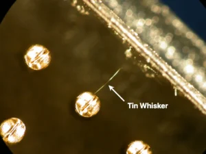
Leaded vs Lead-Free Solder: the Short Answer Measured on reliability, tin-lead solder is still the better alloy. In the NASA-DoD Lead-Free Electronics Project, one of the largest comparative test programs of its kind, tin-lead joints generally outlasted their lead-free counterparts in high-stress environments across 6,755 components, and lead-free held its own only in gentler conditions, steady temperatures, little vibration or shock [10]. The reason why lead-free solder nevertheless dominates the market today compared to leaded solder is more health-related than technical, because when the EU’s RoHS Directive restricted the lead content
A custom cable assembly passes through three stages: design, manufacture, and test. On most production lines those stages run on three separate sets of data: a schematic, a set of build notes, and a test program, each maintained separately and each able to drift out of agreement with the others. A wire gauge that was correct on the drawing and wrong on the build sheet. A pin reassigned in design but never updated in the test program. These differences rarely surface on the bench, they surface in service. Our in-house Test
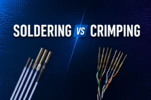
Wire Termination Methods — Crimping and Soldering Crimping is the controlled mechanical compression of a contact barrel around a conductor to create a permanent electrical and mechanical termination [3][4]. NASA defines soldering as “the process of joining clean metallic surfaces through the use of solder without direct fusion of the base metals” [2]. In high-reliability cable and harness work, the standards cited here generally prefer crimping for removable contacts and many splice applications, but soldered contacts are also used where the connector design, contact style, or assembly requirement calls for them
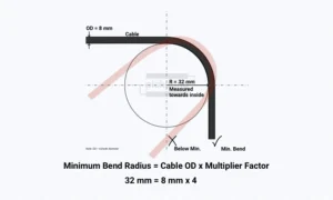
What Is Bend Radius in a Cable – Definition Bend radius is the minimum radius a cable, wire, or harness can be bent to, either temporarily or permanently, without causing permanent damage or reducing performance, power, or reliability [14]. If the actual bend in your installation is equal to or larger than this limit, the cable is within spec. If it is tighter, you risk damaging conductors, insulation, or shielding, and in geometry-sensitive cables you may also distort the electrical geometry [11][12]. In practice, you should aim to keep bends above
A custom cable assembly passes through three stages: design, manufacture, and test. On most production lines those stages run on three separate sets of data: a schematic, a set of build notes, and a test
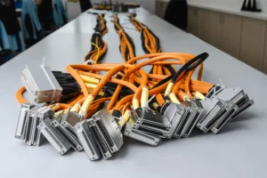
Wire Termination Methods — Crimping and Soldering Crimping is the controlled mechanical compression of a contact barrel around a conductor to create a permanent electrical and mechanical termination [3][4]. NASA defines soldering as “the process
What Is Bend Radius in a Cable – Definition Bend radius is the minimum radius a cable, wire, or harness can be bent to, either temporarily or permanently, without causing permanent damage or reducing performance,
Get the latest articles and custom cable design insights straight to your inbox.