 Skip to content
What Is Bend Radius in a Cable – Definition
Bend radius is the minimum radius a cable, wire, or harness can be bent to, either temporarily or permanently, without causing permanent damage or reducing performance, power, or reliability [14]. If the actual bend in your installation is equal to or larger than this limit, the cable is within spec. If it is tighter, you risk damaging conductors, insulation, or shielding, and in geometry-sensitive cables you may also distort the electrical geometry [11][12].
In practice, you should aim to keep bends above the minimum, not right at it. That extra margin helps absorb installation tolerances, temperature effects, vibration, and the fact that real cable routes are rarely as clean as the drawing [13].
How to Calculate Minimum Bend Radius – Formula Explained
The basic diameter-based calculation method
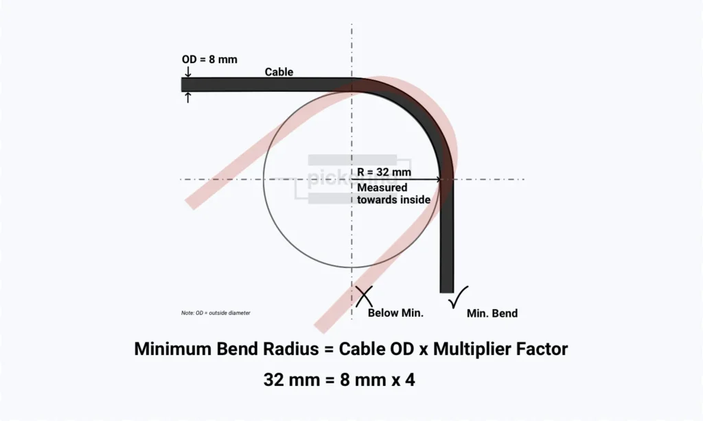
Most standards and manufacturer datasheets express minimum bend radius as a multiple of the cable’s outer diameter (OD) [1][9][15]:
Minimum Bend Radius = Cable OD × Multiplier Factor
The reason for this convention is physical: as cable diameter grows, so does the amount of material that has to stretch, compress, and hold geometry through the bend [13]. The OD is a measured or datasheet value for the finished cable. The required multiplier may come from the governing standard, the cable manufacturer’s documentation, or approved engineering documentation. In a harness, bend-radius compliance should be based on the most sensitive conductor and the largest applicable required bend radius, unless documented approved criteria define otherwise [19].
The multiplier itself varies by cable type, shielding, insulation system, and whether the cable is being installed, held in a static bend, or repeatedly flexed in service [2][9]. For example: a shielded multiconductor cable with a 12 mm outer diameter, specified at a 12x multiplier, has a minimum bend radius of 144 mm.
Why Bend Radius Is a Real Engineering Constraint
Every cable assembly has a limit to how tightly it can be bent before something inside starts to degrade. That limit is the minimum bend radius — a mechanical constraint with direct consequences for signal integrity, insulation life, and long-term reliability [2][13]. Tight bending can damage every layer of a cable’s construction:
- Conductors — strands on the outside of the bend are in tension, on the inside compressed. Cyclic bending fatigues copper progressively, raising resistance before a complete open develops [8][12].
- Insulation — repeated bending fatigues insulation until it cracks, especially at temperature extremes where compounds like PVC become less flexible [5][12].
- Shielding — foil shields can crack under repeated bending; damaged foil or braid reduces shielding effectiveness [12][16].
- Internal geometry — in coaxial and high-speed data cables, bending distorts the cross-section and changes impedance, with effects that worsen at higher frequencies [11].
The challenge is that this damage is often progressive and latent — hidden behind intact outer jackets until thermal cycling, vibration, or time drives it to functional failure [3][12][13]. Installation increases the risk of damage because cables are subjected to significant stress during pulling, and both bend-radius and pulling-tension limits must be controlled during installation [3][17]. In defense and aerospace, where vibration, temperature extremes, and field maintenance are constant, latent bend-radius damage compounds over time. The real cost is rarely the cable itself but the system downtime and troubleshooting effort that follow.
How to Measure Bend Radius
Where bend radius is measured from
For cable and wire harness work, bend radius is most commonly measured along the inside curve of the bend. IPC/WHMA-A-620E defines it exactly that way: “Bend radius is measured along the inside curve of the wire or wire bundles” [15]. That is the convention you will encounter in most harness inspection and acceptance situations.
Not all sources use the same term, though. Some express limits as bend diameter (twice the radius) rather than bend radius — a convention that is common in fiber optics, where pulleys, capstans, and storage loops make diameter the more practical unit [3]. When comparing an installed cable against a specification, make sure you are working in the same units as the governing document. A value pulled from one source without checking whether it specifies radius or diameter can introduce a factor-of-two error in either direction.
How to measure bend radius — practical steps
On a completed assembly or installed harness, bend radius measurement is straightforward in principle but requires care in practice:
- Identify the tightest bend — the point of maximum curvature. This is typically near connectors, at entry/exit points through bulkheads, at tie-down locations, and at any point where the cable changes direction abruptly.
- Measure the bend using the same convention as the governing specification. For a simple circular bend, this can be done with a radius gauge, a template, or by fitting a circular arc to the cable path and measuring its radius. For complex three-dimensional bends, sectional measurement or optical methods may be needed.
- Compare against the specification — either the cable manufacturer’s datasheet value, the applicable standard, or the design drawing callout, whichever governs the product and is most restrictive [1][2][4]. When calling out bend radius on drawings, it is usually better to specify an absolute value (for example, “MIN BEND RADIUS 45 mm”) rather than only a multiplier such as “6× OD.” That gives installers and inspectors a directly usable requirement without requiring them to look up the cable OD and calculate the value in the field.
The most common ways to physically take the measurement are a radius gauge or template, a chord-and-sagitta measurement, and formboard pins or mandrels. A radius gauge or template uses a set of curved profiles held against the inside of the bend until one matches. A chord-and-sagitta measurement uses the straight-line chord across the bend and the depth from the chord to the curve to calculate the radius, which is useful when a gauge cannot reach the bend. In harness manufacture, bends may also be formed around formboard pins or mandrels of known radius, so the bend radius is built into the process rather than checked after the fact.
As a simple workshop check, a spare piece of the same cable can also be formed into a reference loop at the minimum allowed bend, then used for a simple visual comparison. This is useful for a rough visual check, but it is less precise than a gauge, template, or calculated measurement.
Common mistakes when measuring cable bend radius
Mixing measurement conventions. If one source gives a minimum inside bend radius and another illustrates bend diameter or a different reference geometry, it is easy to think you have margin when you do not.
Measuring only in the obvious places. Engineers tend to check the large, visible bends and miss the tight radius that formed where a cable was forced around a clamp, pushed past a bracket edge, or routed through a cable tie placed too close to a connector.
Measuring after dressing, not during. The act of closing a panel, tightening a tie-down, or mating a connector can change the cable’s routing and create a tighter bend than existed when the measurement was taken. The installed condition after final assembly is what matters.
Ignoring the third dimension. On a formboard or in a 2D drawing, bends appear to be in-plane. In the actual assembly, cables twist and route in three dimensions. A bend that looks acceptable in a side view may have a compound curve with a tighter effective radius.
Bend radius charts: typical multipliers by cable type
Two standards provide particularly useful bend radius tables for cable assemblies and wire harnesses. NASA-STD-8739.4A, used in aerospace and defense workmanship, gives both an optimum (design target) and a minimum (hard limit). IPC/WHMA-A-620E, widely used for industry acceptance, organises its requirements by product class. They overlap on some cable types and complement each other on others.
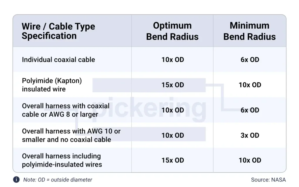
NASA-STD-8739.4A bend radius table for completed harnesses
NASA states that its Table 7-1 values apply to bending that occurs in the installed interconnecting harness or cable [1]. The table is useful because it distinguishes an optimum bend radius from the minimum bend radius. In practice, that means design to the optimum when you can and treat the minimum as the lower limit, not the target.
IPC/WHMA-A-620E bend radius table — class-based minimums
IPC/WHMA-A-620E organises bend-radius acceptance by wire/cable type and product class — Class 1 for general-purpose electronics, Class 2 for dedicated-service products where continued performance is expected, and Class 3 for high-reliability applications where failure is not acceptable. That matters because some bend radius requirements apply across all classes, while others are only established for Class 3 [15].
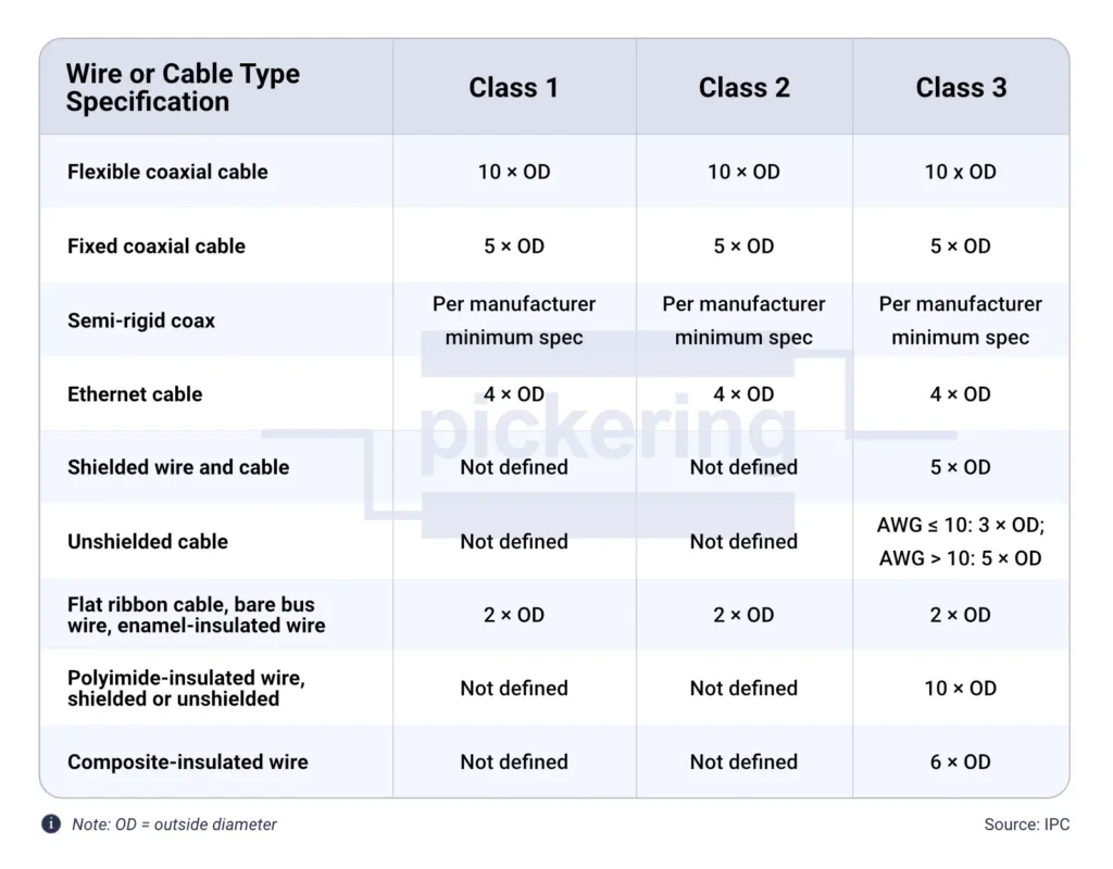
A few distinctions in this table are worth noting. IPC defines “flexible” coax as cable that is or may be flexed during equipment operation, and “fixed” coax as cable secured against movement — so the choice between 10x and 5x depends on whether the cable will ever move in service, not just whether it’s a flexible construction. Semi-rigid coax gets no generic multiplier at all; IPC requires the manufacturer’s stated minimum. The composite insulation row applies specifically to AS22759/80 through /92 and /180 through /192 wire specifications [15].
Static vs Dynamic Bend Radius
The distinction between static and dynamic bend radius is one of the most consequential, and most frequently misunderstood, aspects of cable assembly design.
Static bend radius in fixed installations
Static bend radius applies to cables installed in a fixed position that will not move in service. The bend taken during installation is the bend the cable holds for the life of the system. Most multiplier values in the tables above are essentially static values unless the source says otherwise.
Static does not mean stress-free. A cable at its minimum static bend radius is permanently loaded — conductors in tension, insulation stretched, shield deformed. Thermal cycling and vibration-induced micro-motion still fatigue pre-stressed copper over time, which is why building margin above the minimum is good practice even in static applications.
Dynamic bend radius in repeated-flex applications
Dynamic bend radius applies to cables that flex repeatedly in service or maintenance rather than remain fixed after installation [7][8], for example at hinges, in drag chains, across service loops, or anywhere the cable moves during operation or maintenance. Each flex cycle adds fatigue damage, so the cumulative effect is fundamentally different from a single static bend.
The numbers reflect this. Belden lists 34.8 mm for installation and 65.25 mm for flexing on one high-flex control cable; Cicoil lists 1.26 in for flexible routing and 2.1 in for continuous-motion use on its high-flex HDMI cable [9][10]. A static bend happens once; a dynamic bend happens thousands or millions of times, and every cycle adds to the cumulative fatigue damage. The margin question also differs — cable guides and drag chains can develop wear or misalignment over time, allowing tighter bends than the original design intended. Design for the worst case the cable will actually experience, not the nominal case in the CAD model.
Where dynamic bend radius failures concentrate
- Hinge points and access panels
- Drag chains and energy chains
- Service loops disturbed during maintenance
- Connector-to-cable transitions without adequate strain reliefStrain ReliefA connector device that clamps the cable/wire bundle to the connector so mechanical loads bypass the contact and cable terminations.
- Slip rings and rotary joints
How Cable Type Affects Minimum Bend Radius
Not all cables are created equal, and a single bend radius rule cannot cover the range of constructions that appear in a complex cable assembly. The internal structure of the cable determines which failure mode dominates when it is bent too tightly.
Coax cable bend radius considerations
Coaxial cables are uniquely sensitive to bending because their electrical performance depends on the precise geometric relationship between the center conductor and the outer shield. Tight bending distorts the cross-section and creates a localised impedance discontinuity [11].
The consequences are measurable and frequency-dependent. Microwave Journal notes that bending changes a coaxial cable’s impedance and insertion loss, and that the effect becomes more significant at higher frequencies [11].
For harness work, NASA-STD-8739.4A gives individual coaxial cable a 10x OD optimum bend radius and a 6x OD minimum [1]. IPC/WHMA-A-620E requires 10x OD for flexible coax and 5x OD for coax secured against movement. For semi-rigid coax, IPC does not assign a generic multiplier and instead requires the manufacturer’s stated minimum bend radius [15].
A bend that damages the shield can reduce shielding effectiveness and, in RF-sensitive cables, may also degrade electrical performance [11][12].
Bend radius of fiber optic cable
Fiber optic cable is a special case. NASA-STD-8739.5A defines a long-term bend radius (installed, no tensile load) and a short-term bend radius (during installation under load), with not less than 10x cable diameter recommended for long-term bends [18]. FOA gives 20x during pulling and 10x after installation as its standard recommendation [3]. Always check the specific cable’s datasheet — some fiber cables specify 15x rather than 20x under tension [3].
High-voltage cable bend radius considerations
For power cables over 1,000 V, bend-radius guidance becomes more conservative. Anixter’s NEC / ICEA summary lists 8x OD for single or multiconductor cables without metallic shielding, 12x OD for shielded single-conductor cables, and the greater of 12x individual conductor OD or 7x overall OD for multiconductor cables with individually shielded conductors [2]. The extra margin protects both insulation and shielding geometry.
HDMI cable bend radius and other data and video cables
High-speed data cables such as Ethernet, USB, HDMI, and DisplayPort rely on controlled internal geometry. Tight bends disturb pair spacing and other internal relationships, which is why bend-radius guidance for these cables is fundamentally about maintaining electrical geometry, not just avoiding obvious mechanical damage.
HDMI is a good example of why manufacturer data matters. There is no single universal HDMI bend-radius number that applies across all products; vendors publish their own limits. Cicoil, for example, lists 1.26 in for flexible use and 2.1 in for continuous-motion use for its high-flex HDMI cable [10].
The general principle for all data cables is the same: the tighter the electrical geometry and the higher the data rate, the less room there is for distortion.
Why cable construction changes the safe bending limit
Two cables with the same outer diameter, the same voltage rating, and the same conductor count can have significantly different minimum bend radii because of differences in:
- Strand count. A conductor made of many fine strands distributes bending stress more evenly than one made of fewer, thicker strands. Higher strand counts generally tolerate bending better [7].
- Shield type. A braided shield is mechanically more tolerant of bending than a foil shield, which is more prone to damage under heavy flexing [12].
- Insulation material. PTFE retains useful properties across a much wider temperature range than PVC. The safe bending limit for a PVC-insulated cable in the cold can be dramatically different from its room-temperature value [5][6].
- Jacket construction. A cable with a thick, rigid jacket resists bending more than one with a thin, flexible jacket — but the rigid jacket also transmits more force to the internal components when bent.
- Operating temperature. A cable that bends safely at room temperature may not at low temperatures, where insulation and jacket materials stiffen [5][6].
- Static vs. repeated flex. A cable installed in a fixed position can tolerate a tighter bend than one that flexes repeatedly in service [7][9].
Beyond individual cable construction, harness geometry can matter as much as material selection. In a concentric-twisted harness, conductors are arranged in symmetrical layers that spiral around a central core rather than running in a loose or irregular bundle. That uniform arrangement helps distribute bending strain more evenly across the harness and can improve overall flexibility. In tight routing paths, the result is fewer localized stress concentrations on any single conductor, even though the formal bend-radius requirement still depends on the governing cable or conductor specification.
All of the above is why manufacturer datasheets are the authoritative source for minimum bend radius on specific cables, and why generic multiplier tables are starting points — not answers [3][4][9][10]. The generic rule is a screening tool; the cable’s datasheet is the specification.
In a harness containing multiple cable types, the minimum bend radius is governed by the most restrictive component. Both IPC/WHMA-A-620E and NASA workmanship guidance treat the most demanding cable in the assembly as the governing one [1][15]. The practical rule is to start with the governing standard, then check the specific cable’s datasheet and use whichever value is more conservative [1][15]. When different sources give different numbers for what looks like the same cable type, it usually reflects different assumptions — not an error.
References
- NASA, NASA-STD-8739.4A: Workmanship Standard for Crimping, Interconnecting Cables, Harnesses, and Wiring. 2016. https://standards.nasa.gov/standard/NASA/NASA-STD-87394
- Anixter, “Minimum Bend Radius.” https://www.anixter.com/en_ca/resources/literature/wire-wisdom/minimum-bend-radius.html
- The Fiber Optic Association, “Installing Fiber Optic Cable – Bend Radius.” https://foa.org/tech/ref/install/bend_radius.html
- trueCABLE, “Obey the Bend: Bending Radius of Cable,” 2023. https://www.truecable.com/blogs/cable-academy/minimum-bend-radius
- SAB Cable, “Insulation & Sheath Material Polyvinylchloride (PVC) for Cables and Wires.” https://www.sab-cable.com/cables-wires-harnessing-temperature-measurement/technical-data/cables-and-wires/polyvinylchloride-pvc.html
- Habia, “PTFE cable material.” https://www.habia.com/en/products/manufacturing-competence/materials/ptfe-cable-material/
- New England Wire Technologies, “Ultra Flexible Strands.” https://www.newenglandwire.com/product/ultra-flexible-strands/
- T. Knych, B. Smyrak, and B. Jurkiewicz, “A Comparative Analysis of the Fatigue Strength of Aluminium and Copper Wires Used for Power Cables,” Materials 18, no. 18 (2025): 4426. https://doi.org/10.3390/ma18184426
- Belden, “HF2X1.5CY – Flexible Automation Cable.” https://catalog.belden.com/index.cfm?event=pd&p=PF_HF2X15CY
- Cicoil, “HDMI High Flex Cable.” https://www.cicoil.com/hdmi-cable/flex
- Katerina Galitskaya, “What Happens If We Bend a Coaxial Cable,” Microwave Journal. https://www.microwavejournal.com/blogs/31-simulation-advice-katerina-galitskaya/post/41160-what-happens-if-we-bend-a-coaxial-cable
- Amphenol TPC Wire & Cable, “Understanding Why Cable Fails,” 2022. https://www.tpcwire.com/blog/understanding-why-cable-fails
- Lectromec, “Minimum bend radius as applied to aircraft wire system degradation,” 2013. https://lectromec.com/minimum-bend-radius-as-applied-to-aircraft-wire-system-degradation/
- IPC-D-620A, Design and Critical Process Requirements for Cable and Wiring Harness Assemblies. IPC, 2021.
- IPC/WHMA-A-620E, Requirements and Acceptance for Cable and Wire Harness Assemblies. IPC/WHMA, 2022.
- Cordial, “Foil Shields.” https://www.cordial-cables.com/en/foil-shields
- MSFC Ad Hoc Committee, Manufacture and Quality Control of Interconnecting Wire Harnesses, Volume I of IV, NASA TM X-64685, Sep. 1, 1972.
- NASA, NASA-STD-8739.5A: Workmanship Standard for Fiber Optic Terminations, Cable Assemblies, and Installation. 2015.
- IPC, IPC-HDBK-620: Handbook and Guide to IPC-D-620 and IPC/WHMA-A-620. Bannockburn, IL, USA: IPC, Apr. 2018.
