author
Our content is written with respect for established industry norms and best practices in cable design and manufacturing. We start with real engineering questions and aim to answer them in a clear, structured way, using consistent terminology and practical examples. The goal is to reflect how cable assemblies are typically specified, designed, built, and used in real applications, so the information is useful beyond theory.
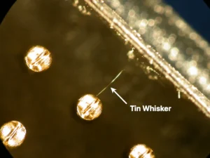
Leaded vs Lead-Free Solder: the Short Answer Measured on reliability, tin-lead solder is still the better alloy. In the NASA-DoD Lead-Free Electronics Project, one of the largest comparative test programs of its kind, tin-lead joints generally outlasted their lead-free counterparts in high-stress environments across 6,755 components, and lead-free held its own only in gentler conditions, steady temperatures, little vibration or shock [10]. The reason why lead-free solder nevertheless dominates the market today compared to leaded solder is more health-related than technical, because when the EU’s RoHS Directive restricted the lead content
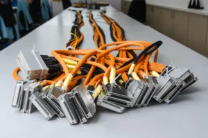
A custom cable assembly passes through three stages: design, manufacture, and test. On most production lines those stages run on three separate sets of data: a schematic, a set of build notes, and a test program, each maintained separately and each able to drift out of agreement with the others. A wire gauge that was correct on the drawing and wrong on the build sheet. A pin reassigned in design but never updated in the test program. These differences rarely surface on the bench, they surface in service. Our in-house Test
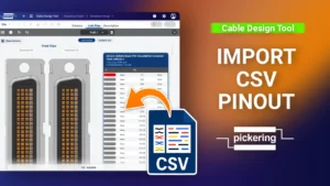
Cable Design Tool Tutorial The Cable Design Tool lets you import a complete pinout from a CSV file instead of linking every pin by hand. For cable assemblies with a large number of conductors, this is the faster and safer route: you build the pinout in a spreadsheet and bring it in all at once. This guide covers the full workflow, from exporting a template CSV to importing pinouts for twisted pair cables. Step 1 Make sure the basics are in place Before using the CSV import, you’ll need the cable
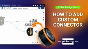
Cable Design Tool Tutorial The Cable Design Tool lets you add custom connectors directly in your design when the part you need isn’t in the library. This guide covers the full process, from creating the connector to linking its pins in the pinout view. Step 1 Open the custom connector editor First, right click an empty space on the canvas to add a connector, then click Select Connector to open the filter view. Search for your connector. If nothing matches, the Create custom connector button appears. You can also start one
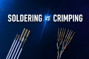
Wire Termination Methods — Crimping and Soldering Crimping is the controlled mechanical compression of a contact barrel around a conductor to create a permanent electrical and mechanical termination [3][4]. NASA defines soldering as “the process of joining clean metallic surfaces through the use of solder without direct fusion of the base metals” [2]. In high-reliability cable and harness work, the standards cited here generally prefer crimping for removable contacts and many splice applications, but soldered contacts are also used where the connector design, contact style, or assembly requirement calls for them
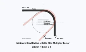
What Is Bend Radius in a Cable – Definition Bend radius is the minimum radius a cable, wire, or harness can be bent to, either temporarily or permanently, without causing permanent damage or reducing performance, power, or reliability [14]. If the actual bend in your installation is equal to or larger than this limit, the cable is within spec. If it is tighter, you risk damaging conductors, insulation, or shielding, and in geometry-sensitive cables you may also distort the electrical geometry [11][12]. In practice, you should aim to keep bends above
Get the latest articles and custom cable design insights straight to your inbox.