 Skip to content
Wire Termination Methods — Crimping and Soldering
Crimping is the controlled mechanical compression of a contact barrel around a conductor to create a permanent electrical and mechanical termination [3][4]. NASA defines soldering as “the process of joining clean metallic surfaces through the use of solder without direct fusion of the base metals” [2]. In high-reliability cable and harness work, the standards cited here generally prefer crimping for removable contacts and many splice applications, but soldered contacts are also used where the connector design, contact style, or assembly requirement calls for them [1][3][4][5].
For wire-to-contact and many wire-to-wire terminations, crimping is the default method in these standards. The sections below explain why — and identify the cases where solder is still appropriate [1][3][4].
Crimp vs Solder — Performance Comparison
Mechanical strength and vibration resistance
For harnesses and cables that may be pulled, flexed, or be exposed to vibration, a properly made crimp is usually the better choice from a mechanical standpoint. A properly formed crimp is evaluated by pull testing, meaning the wire is physically pulled to confirm the crimp can withstand a minimum force, not just by visual appearance: NASA-STD-8739.4A requires crimp pull strengths to meet minimum values by wire gauge, and failures below those values are rejects [1]. Selected values from NASA Table 12-1:
| Conductor Size (AWG) | Minimum Tensile Strength, N (lb) |
| 28 | 22 (5) |
| 26 | 36 (8) |
| 24 | 36 (8) |
| 22 | 57 (13) |
| 20 | 92 (21) |
| 18 | 142 (32) |
| 16 | 183 (41) |
Values for copper and high-strength copper alloy stranded conductors [1].
Soldered conductors behave differently under mechanical stress. NASA-STD-8739.4A states that stranded conductors will experience solder wicking during attachment, leaving the conductor rigid up to the point where wicking stops and flexible beyond it; wire movement then concentrates stress at that transition and can produce conductor fatigue and failure [1]. In practice, the concern is not just the geometric transition but the heat-affected zone immediately behind the soldered section: at soldering temperatures, the copper in that area can harden, lose ductility, and become more brittle than the wire beyond it. Combined with solder wicking, that leaves a stiff-to-flexible transition where repeated bending or vibration tends to damage the conductor just behind the soldered area rather than in the solder fillet itself. NASA-STD-8739.3 separately lists fractured and disturbed solder connections as rejection conditions [2].
Electrical performance and contact resistance
From an electrical standpoint, properly made soldered and crimped terminations can both perform very well. The standards reviewed here treat both as valid when the termination matches the contact design and is made correctly [1][2][3].
In practice, real-world differences often come down more to workmanship, process control, and mechanical reliability than to any blanket advantage in pure resistance [1][2][3].
Thermal cycling and environmental durability
Thermal cycling and vibration are well-established durability concerns for soldered joints in the academic literature [6][7][8].
Furthermore, IPC-HDBK-620 explains why crimping solder-tinned stranded wire is restricted in high-reliability work: solder acts as a malleable, variable-thickness lubricant, deforms under pressure, and recrystallizes under temperature cycling, degrading the crimp termination [4]. Consistent with that rationale, IPC-D-620A states that crimp termination of solder-tinned stranded wire and over-soldering of completed crimp terminations is prohibited [3]. NASA-STD-8739.4A also warns that solder wicking creates a rigid-to-flexible transition where movement can concentrate stress and produce conductor fatigue and failure [1].
Why not crimp AND solder?
As a general rule, high-reliability standards are clear: do not improve a completed crimp by adding solder afterward. Applying soldering temperatures to a completed crimp anneals the compression zone, relaxing the gas-tight cold-weld developed during the crimping process [4]. The solder also cannot flow into the compression zone to wet all contact-conductor surfaces, so the result fails the acceptance requirements for both a crimped termination and a soldered termination [4]. Over-soldering of completed crimp terminations is prohibited for space and Class 3 applications [3].
The exception is a contact or assembly that is designed by the manufacturer to use both operations. Some wire-to-board contacts, for example, crimp the conductor first for wire retention and insulation support, then solder the crimped terminal into a PCB as part of the approved termination design. In those cases, the manufacturer’s documented tooling, process, and acceptance criteria govern the assembly; the problem is uncontrolled soldering of a normal completed crimp, not every engineered crimp-and-solder contact system.
When to Crimp vs Solder — Selection by Application
Crimping is the default
IPC-HDBK-620 is direct: “Connectors using removable crimp contacts are preferred to solder contact types” [4]. IPC-D-620A likewise states that, as a preferred practice, crimp-type wire splices are recommended for higher reliability [3].
NASA-STD-8739.4A states that crimped contacts shall be used with stranded wire only; solid wire and solid, tinned wire shall not be used with crimped contacts [1]. IPC-D-620A likewise requires wire terminations to be compliant with the connector or terminal’s termination technology [3], and IPC-HDBK-620 treats crimping of solid wire and solder-tinned stranded wire as special cases requiring prior approval [4].
Soldering Applications — Where Solder Is Still the Right Choice
Solder remains the correct termination method in several applications, including:
- Solder cup contacts — non-removable solder cups, including hermetic and environmental connectors, where the connector design uses soldered contacts [1].
- Board and terminal soldering — J-STD-001 / J-STD-001FS covers soldered wires, terminals, and printed wiring assembly terminations, including PCB-related soldered connections [5].
- Shield terminations — solder sleeves are one of the acceptable methods for terminating individual cable shields [1].
- Fine-gauge repairs — repair of stranded wiring smaller than 28 AWG should be performed using a solder splice [4].
- Compact splices — solder splices can produce a smaller physical profile than crimp splices in dense bundles [4].
Good Crimp vs Bad Crimp — Acceptance Criteria
Crimp acceptance is typically controlled by 100 percent visual inspection and tensile pull testing against minimum force values defined by the applicable standard (e.g., NASA-STD-8739.4A, IPC/WHMA-A-620) or terminal manufacturer [1]. For production quality control, the tool/contact-conductor combination is pull-tested at the start and end of each work shift or production run, and production shall not proceed until there are zero failures out of three samples tested [1].
Exact acceptance and rejection criteria depend on the contact style, terminal design, manufacturer instructions, and applicable workmanship standard. The examples below are representative criteria for machined/removable crimp contacts.
Good crimp — acceptance criteria for machined/removable crimp contacts [1]:
- Contact deformed only by tool indentations
- Crimp indents properly located in the correct area of the contact
- Wire strands visible in inspection hole of barrel
- Metal ferrules tightly and symmetrically crimped
- Insulation clearance within specification
- Contact plating intact — no cracks, flaking, or exposed base metal
- Pull test meets or exceeds minimum tensile strength for the wire gauge
Bad crimp — rejection criteria for machined/removable crimp contacts [1]:
- Cracks in crimp barrel
- Damaged or deformed crimp contact
- Crimp indents not located in the correct area on the contact
- Wire strands not visible in inspection hole
- Birdcaging of conductor
- Peeling or flaking of plating on contact
- Tarnished, corroded, or contaminated contact
- Improper insulation clearance
- Insulation whiskers extending into the crimp barrel
- Metal ferrules crimped with improper alignment
- Pull test below minimum tensile strength
Crimp quality is a process-control issue
Crimp quality depends on more than the tool itself — it requires controlled tooling, trained personnel, and verified processes working together. NASA-STD-8739.4A makes that concrete by requiring controlled hand crimping tools: full-cycle ratcheting tools with four or more indenter blades, calibration adjustments accessible only when the tool is disassembled, and sealed or locked settings verified before use [1]. NASA-STD-8739.6 adds program-level manufacturing, quality, and training requirements [9].
In production, automation reduces the human variability that manual crimping introduces. Semi-automatic and fully automatic crimp platforms integrate cutting, stripping, and crimping into a single traceable process. Crimp force monitoring and analysis systems, often described as CFM or in some equipment/software as CFA/CFA+ data, measure the force curve during each crimp cycle to detect errors such as missing strands, faulty terminals, or crimped insulation in real time [10]. Schleuniger’s discussion of CFM identifies wire preparation, stripping consistency, and wire presentation to the stop position as major sources of variation in manual crimping. These are exactly the steps that automation controls [11]. Newer automated quality systems can also add camera-based visual inspection of wire ends, detecting defects such as damaged ferrules, excess strands from over-stripping, and protruding strands outside the ferrule collar as part of the production process [12].
Good Solder Joint vs Bad Solder Joint — Acceptance Criteria
Solder acceptance is assessed visually against criteria defined by the applicable standard (e.g., NASA-STD-8739.3, IPC/WHMA-A-620, J-STD-001). A conforming solder joint shows evidence of proper wetting, fillet formation, and an undisturbed finish, with no signs of the defect conditions listed below [2]. The criteria below use NASA-STD-8739.3 as a concrete, publicly accessible example; other standards may define slightly different acceptance and rejection criteria.
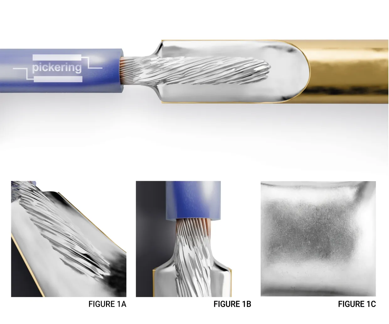
Good solder joint — acceptance criteria [2]:
- Solder wets all elements of the connection
- Smooth, nonporous, undisturbed surface [Fig. 1C]
- Satin to bright finish [Fig. 1C]
- Complete fillet around the periphery [Fig 1B]
- Lead contour visible [Fig 1A]
- Stress relief present in leads or conductors between points of constraint
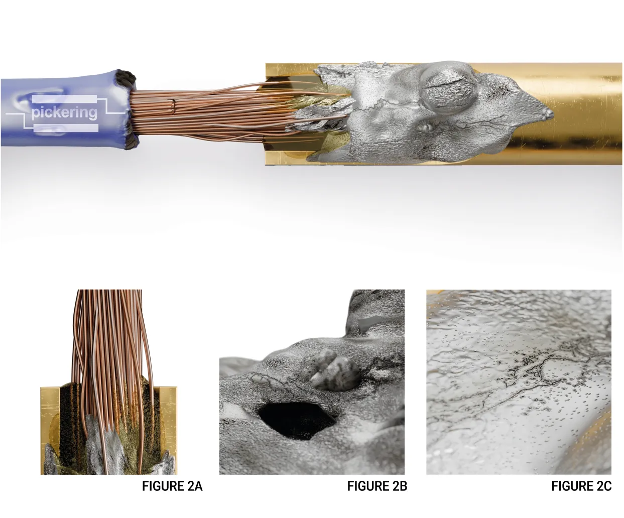
Bad solder joint — rejection criteria [2]:
- Cold solder connection (grayish, porous) [Fig. 2C]
- Overheated solder connection [Fig. 2C]
- Fractured or disturbed joint [Fig. 2C]
- Poor wetting, dewetting, or nonwetting
- Blowholes, pinholes, or voids [Fig. 2B]
- Excessive or insufficient solder [Fig. 2A]
- Flux residue or other contaminants [Fig. 2A]
- Improper tinning of leads or conductors
- Separation of wire strands (birdcaging) [Fig. 2A]
- Improper wrap or stress relief
Crimping and Soldering Standards — Quick Reference
| Standard | Scope | Key Provisions |
| IPC/WHMA-A-620 | Requirements and acceptance for cable and wire harness assemblies | Manufacturing workmanship and acceptance criteria for cable and wire harness assemblies |
| J-STD-001 / J-STD-001FS | Soldered electrical and electronic assemblies | Solder joint requirements; FS = space addendum |
| NASA-STD-8739.4A | Crimping, interconnecting cables, harnesses, and wiring | Pull-test tables, tool control, 100% crimp inspection |
| NASA-STD-8739.3 | Soldered electrical connections | Solder connection workmanship and acceptance/rejection criteria |
| NASA-STD-8739.6 | Implementation requirements for NASA workmanship standards | Manufacturing, quality, and training requirements that augment NASA workmanship standards |
NASA workmanship standards impose requirements above the general IPC baseline: 100% visual inspection of every crimped connection [1], mandatory full-cycle ratcheting tools [1], pull testing at the start and end of each work shift or production run [1], and documented manufacturing, quality, training, and process-control requirements through NASA-STD-8739.6 [9].
Conclusion
Across the standards reviewed here, crimping is the default choice for most removable-contact and many wire-splice terminations because the process is tightly controlled for pull strength, tooling, and inspection [1][3][4]. Solder remains essential where the hardware is designed for solder cups, board-level terminations, shield sleeves, or very small-gauge repairs [1][4][5]. In practice, reliability depends on choosing the right termination for the hardware and controlling the process well.
References
[1] NASA, NASA-STD-8739.4A w/Change 4: Workmanship Standard for Crimping, Interconnecting Cables, Harnesses, and Wiring, 2016. https://standards.nasa.gov/standard/NASA/NASA-STD-87394
[2] NASA, NASA-STD-8739.3 w/Change 2: Soldered Electrical Connections, 1997. https://standards.nasa.gov/standard/NASA/NASA-STD-87393
[3] IPC, IPC-D-620A, Design and Critical Process Requirements for Cable and Wiring Harnesses. IPC, 2021.
[4] IPC, IPC-HDBK-620, Handbook and Guide to IPC/WHMA-A-620. IPC, 2018.
[5] IPC, J-STD-001 / J-STD-001FS, Requirements for Soldered Electrical and Electronic Assemblies (with Space Applications Addendum). IPC.
[6] J. A. Depiver, S. Mallik, and D. Harmanto, “Solder joint failures under thermo-mechanical loading conditions – A review,” Advances in Materials and Processing Technologies, vol. 7, no. 1, 2021. https://doi.org/10.1080/2374068X.2020.1751514
[7] N. Ismail, W. Y. W. Yusoff, A. Amat, N. A. A. Manaf, and N. Ahmad, “A review of extreme condition effects on solder joint reliability: Understanding failure mechanisms,” Defence Technology, 2024. https://doi.org/10.1016/j.dt.2024.05.013
[8] D. Ghaderi, M. Pourmahdavi, V. Samavatian, O. Mir, and M. Samavatian, “Combination of thermal cycling and vibration loading effects on the fatigue life of solder joints in a power module,” Proceedings of the Institution of Mechanical Engineers, Part L: Journal of Materials: Design and Applications, vol. 233, no. 7, 2019. https://doi.org/10.1177/1464420718780525
[9] NASA, NASA-STD-8739.6: Implementation Requirements for NASA Workmanship Standards. https://standards.nasa.gov/standard/NASA/NASA-STD-87396
[10] Komax Group, “Crimp Force Monitoring.” https://www.komaxgroup.com/en/products/testing-and-quality-tools/cable-and-harness-quality-tools/crimp-force-monitoring
[11] Schleuniger / Connector Supplier, “Crimp Force Monitoring – The Recipe for Success.” https://connectorsupplier.com/schleuniger-addresses-why-crimp-force-monitoring-is-important-100813/
[12] Zoller + Frohlich, “Visual Control System (VCS).” https://www.zofre.de/en/wire-processing/quality-assurance/vcs
