 Skip to content
Minimum Bend Radius in Cables: How to Measure, Calculate, and Apply It
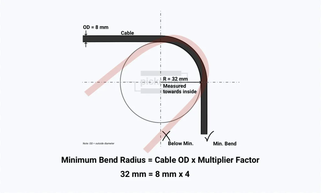
What Is Bend Radius in a Cable – Definition Bend radius is the minimum radius a cable, wire, or harness can be bent to, either temporarily or permanently, without causing permanent damage or reducing performance, power, or reliability [14]. If the actual bend in your installation is equal to or larger than this limit, the cable is within spec. If it is tighter, you risk damaging conductors, insulation, or shielding, and in geometry-sensitive cables you may also distort the electrical geometry [11][12]. In practice, you should aim to keep bends above the minimum, not right at it. That extra margin helps absorb installation tolerances, temperature effects, vibration, and the fact that real cable routes are rarely as clean as the drawing [13]. How to Calculate Minimum Bend Radius – Formula Explained The basic diameter-based calculation method Most standards and manufacturer datasheets express minimum bend radius as a multiple of the cable’s outer diameter (OD) [1][9][15]: Minimum Bend Radius = Cable OD × Multiplier Factor The reason for this convention is physical: as cable diameter grows, so does the amount of material that has to stretch, compress, and hold geometry through the bend [13]. The OD is a measured or datasheet value for the finished cable. The required multiplier may come from the governing standard, the cable manufacturer’s documentation, or approved engineering documentation. In a harness, bend-radius compliance should be based on the most sensitive conductor and the largest applicable required bend radius, unless documented approved criteria define otherwise [19]. The multiplier itself varies by cable type, shielding, insulation system, and whether the cable is being installed, held in a static bend, or repeatedly flexed in service [2][9]. For example: a shielded multiconductor cable with a 12 mm outer diameter, specified at a 12x multiplier, has a minimum bend radius of 144 mm. Why Bend Radius Is a Real Engineering Constraint Every cable assembly has a limit to how tightly it can be bent before something inside starts to degrade. That limit is the minimum bend radius — a mechanical constraint with direct consequences for signal integrity, insulation life, and long-term reliability [2][13]. Tight bending can damage every layer of a cable’s construction: Conductors — strands on the outside of the bend are in tension, on the inside compressed. Cyclic bending fatigues copper progressively, raising resistance before a complete open develops [8][12]. Insulation — repeated bending fatigues insulation until it cracks, especially at temperature extremes where compounds like PVC become less flexible [5][12]. Shielding — foil shields can crack under repeated bending; damaged foil or braid reduces shielding effectiveness [12][16]. Internal geometry — in coaxial and high-speed data cables, bending distorts the cross-section and changes impedance, with effects that worsen at higher frequencies [11]. The challenge is that this damage is often progressive and latent — hidden behind intact outer jackets until thermal cycling, vibration, or time drives it to functional failure [3][12][13]. Installation increases the risk of damage because cables are subjected to significant stress during pulling, and both bend-radius and pulling-tension limits must be controlled during installation [3][17]. In defense and aerospace, where vibration, temperature extremes, and field maintenance are constant, latent bend-radius damage compounds over time. The real cost is rarely the cable itself but the system downtime and troubleshooting effort that follow. How to Measure Bend Radius Where bend radius is measured from For cable and wire harness work, bend radius is most commonly measured along the inside curve of the bend. IPC/WHMA-A-620E defines it exactly that way: “Bend radius is measured along the inside curve of the wire or wire bundles” [15]. That is the convention you will encounter in most harness inspection and acceptance situations. Not all sources use the same term, though. Some express limits as bend diameter (twice the radius) rather than bend radius — a convention that is common in fiber optics, where pulleys, capstans, and storage loops make diameter the more practical unit [3]. When comparing an installed cable against a specification, make sure you are working in the same units as the governing document. A value pulled from one source without checking whether it specifies radius or diameter can introduce a factor-of-two error in either direction. How to measure bend radius — practical steps On a completed assembly or installed harness, bend radius measurement is straightforward in principle but requires care in practice: Identify the tightest bend — the point of maximum curvature. This is typically near connectors, at entry/exit points through bulkheads, at tie-down locations, and at any point where the cable changes direction abruptly. Measure the bend using the same convention as the governing specification. For a simple circular bend, this can be done with a radius gauge, a template, or by fitting a circular arc to the cable path and measuring its radius. For complex three-dimensional bends, sectional measurement or optical methods may be needed. Compare against the specification — either the cable manufacturer’s datasheet value, the applicable standard, or the design drawing callout, whichever governs the product and is most restrictive [1][2][4]. When calling out bend radius on drawings, it is usually better to specify an absolute value (for example, “MIN BEND RADIUS 45 mm”) rather than only a multiplier such as “6× OD.” That gives installers and inspectors a directly usable requirement without requiring them to look up the cable OD and calculate the value in the field. The most common ways to physically take the measurement are a radius gauge or template, a chord-and-sagitta measurement, and formboard pins or mandrels. A radius gauge or template uses a set of curved profiles held against the inside of the bend until one matches. A chord-and-sagitta measurement uses the straight-line chord across the bend and the depth from the chord to the curve to calculate the radius, which is useful when a gauge cannot reach the bend. In harness manufacture, bends may also be formed around formboard pins or mandrels of known radius, so the bend radius is built into the process rather than checked after […]
