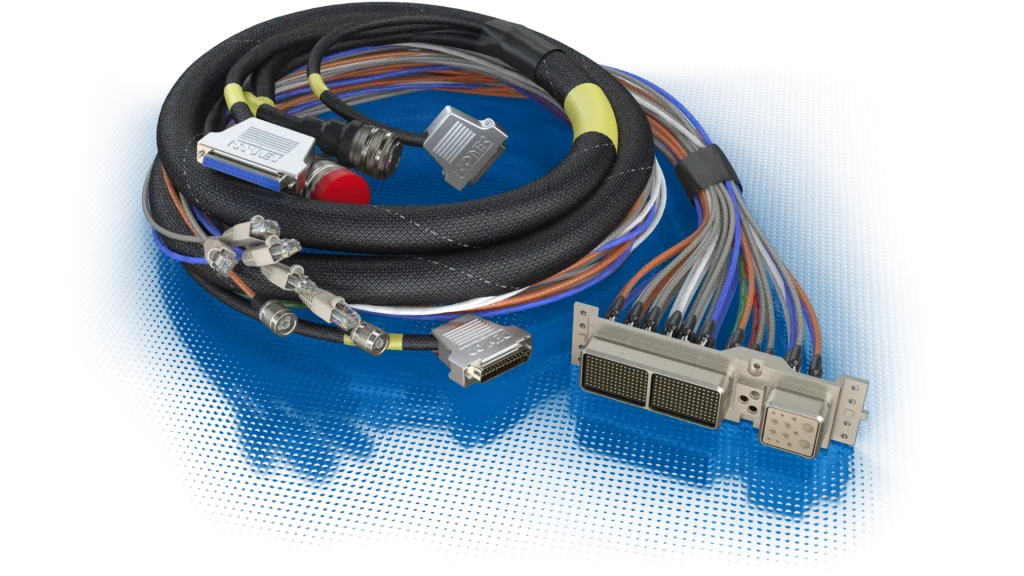
Leaded vs Lead-Free Solder: the Short Answer
Measured on reliability, tin-lead solder is still the better alloy. In the NASA-DoD Lead-Free Electronics Project, one of the largest comparative test programs of its kind, tin-lead joints generally outlasted their lead-free counterparts in high-stress environments across 6,755 components, and lead-free held its own only in gentler conditions, steady temperatures, little vibration or shock [10]. The reason why lead-free solder nevertheless dominates the market today compared to leaded solder is more health-related than technical, because when the EU’s RoHS Directive restricted the lead content in electronics starting in 2006, its goal was to protect people and the environment, not to improve the quality of soldered joints [8].
That is precisely why even the most demanding programs on Earth and in space continue to rely on tin-lead alloys for their projects. NASA’s soldering quality standards have long specified the tin-lead alloys Sn60 and Sn63 [6], and the current standard at the Kennedy Space Center still requires the use of tin-lead alloys for critical ground support electronics [18]. It is also worth noting that the EU’s lead ban does not apply to military or space equipment [8], and a documented failure mode known as “tin whiskers” is a suspected cause of satellite failures in orbit that have been reported in hardware containing pure tin components [12]. The remainder of this article presents evidence to help you choose the right solution for your own project.
What Is Solder Made Of?
Solder is a fusible metal alloy that melts at temperatures below the melting point of the metals it joins, wets them, and, upon solidification, forms an electrically conductive joint. In electronics, there are two main types of solder. The traditional choice is tin-lead (SnPb) solder. The IPC/EIA J-STD-001C standard listed Sn60Pb40, Sn62Pb36Ag2, and Sn63Pb37 as base alloys, while other alloys were permitted in cases where data had demonstrated that they met reliability criteria [4]. The second group, lead-free solder, typically replaces lead with silver and copper, most commonly in the form of the SAC305 alloy, which contains 96.5% tin, 3% silver, and 0.5% copper [14]. The IPC/WHMA-A-620E standard, in turn, uses the SAC305 alloy as the reference lead-free solder bath [1].
| Alloy | Composition | Melting point | Type |
| Sn63Pb37 | 63% Sn, 37% Pb | 183 °C, eutectic [13] | Leaded |
| Sn60Pb40 | 60% Sn, 40% Pb | 183 °C solidus, 190 °C liquidus [23] | Leaded |
| Sn62Pb36Ag2 | 62% Sn, 36% Pb, 2% Ag | 179 °C [24] | Leaded, silver-bearing [1] |
| SAC305 | 96.5% Sn, 3% Ag, 0.5% Cu | 217 °C solidus, 220 °C liquidus [14] | Lead-free |
| SAC387 | 95.5% Sn, 3.8% Ag, 0.7% Cu | 217 °C [27] | Lead-free, high-silver |
| High-melting-point (HMP) | ≥85% Pb | well above Sn63Pb37 | Leaded, RoHS-exempt [7][8] |
Sn63Pb37 is eutectic, meaning it goes from solid to liquid at a single temperature with no plastic range, which is part of why it is so forgiving to work with [13].
Leaded vs Lead-Free Solder Compared
The trade-offs are consistent across sources. What changes is which ones matter for your application.
| Property | Tin-lead (Sn63Pb37) | Lead-free (SAC305) |
| Melting point | 183 °C eutectic [13] | 217–220 °C [14] |
| Process temperature margin | ~35 °C more thermal budget for parts and boards [13][14] | Hotter process, less margin |
| Joint appearance | Shiny to satin, smooth, concave meniscus [1][3] | More likely grainy or dull, greater wetting contact angles [1] |
| Inspectability | Familiar visual baseline [3] | Dull finish is acceptable, not a defect, but inspectors misread it [1][3] |
| High-stress reliability (thermal cycling, vibration) | Generally more reliable [10] | Generally fails first [10] |
| Low-stress reliability | Baseline | Generally outperforms SnPb, mechanical shock excepted [10] |
| Tin-whisker risk | Lead addition suppresses growth [2][11] | Susceptible regime per IPC (<3% Pb) [2] |
| Mixing solders | SnPb rework restores the reliability of a joint built that way from the start [10] | Joints with both alloys in them are the least reliable configuration measured [10] |
| Regulatory status | Banned in RoHS-scope EEE above 0.1% Pb; military/space not covered, HMP alloys exempted [8] | Required to meet the 0.1% Pb limit in RoHS-scope products [8] |
| Health handling | Hygiene-controllable; airborne lead is very low at iron temperatures [15], so hand-to-mouth ingestion is the dominant uptake route [19] | No lead, but hotter process and more flux fume |
Is lead-free solder as good as lead solder?
Not in environments where reliability is most important, but in less demanding conditions, it can be a good alternative. As part of a project by NASA and the U.S. Department of Defense, more than 30 chemical compositions of solder joints were tested on 6,755 components under conditions involving temperature cycling, vibration, drop impacts, and combined loads. For most types of components, control samples with tin-lead solder proved to be more reliable under demanding military conditions. In contrast, under low-stress conditions, lead-free joints generally outperformed SnPb joints, with mechanical shocks being a notable exception to this trend [10]. The report’s introduction openly highlights what is at stake: the approval of lead-free components “produces one of the greatest risks to the reliability of a weapon system” due to new and as yet insufficiently understood failure mechanisms and unknown long-term reliability [10].
What are the disadvantages of using lead-free solder?
The main disadvantages relate to the manufacturing process and reliability, not just workability:
- Higher process temperature. The increase from 183 °C to 217–220 °C consumes roughly 35 °C from the thermal budget previously available to heat-sensitive components, connector bodies, and insulation [13][14].
- Joints that look wrong but aren’t. Lead-free solder joints are more likely to be grainy or dull with greater wetting angles. Both IPC-A-610 and A-620E standards state that dull, matte, or grainy joints, which are typical for a given alloy, are acceptable. In a lead-free production line, it is therefore essential that inspectors undergo retraining on these standards; otherwise, good joints will be unnecessarily reworked for cosmetic reasons [1][3].
- Stiffer failure behavior. Comparative data show that lead-free joints fail earlier under high thermal and vibration stress [10]. The commonly offered explanation is that stiffer SAC alloys transfer more stress into the board and terminations than ductile SnPb alloys, although the test report itself documents the result rather than the mechanism.
- Tin whiskers. Covered in greater detail in the next section.
- Shop-floor friction. In practice, technicians consistently report faster tip erosion and a less forgiving working feel with lead-free alloys. This is based on shop experience rather than measured data, but it is nearly universal.
Tin Whiskers: the Failure Mode That Keeps Lead in Aerospace
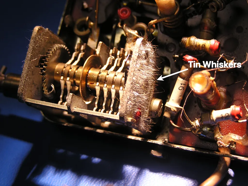
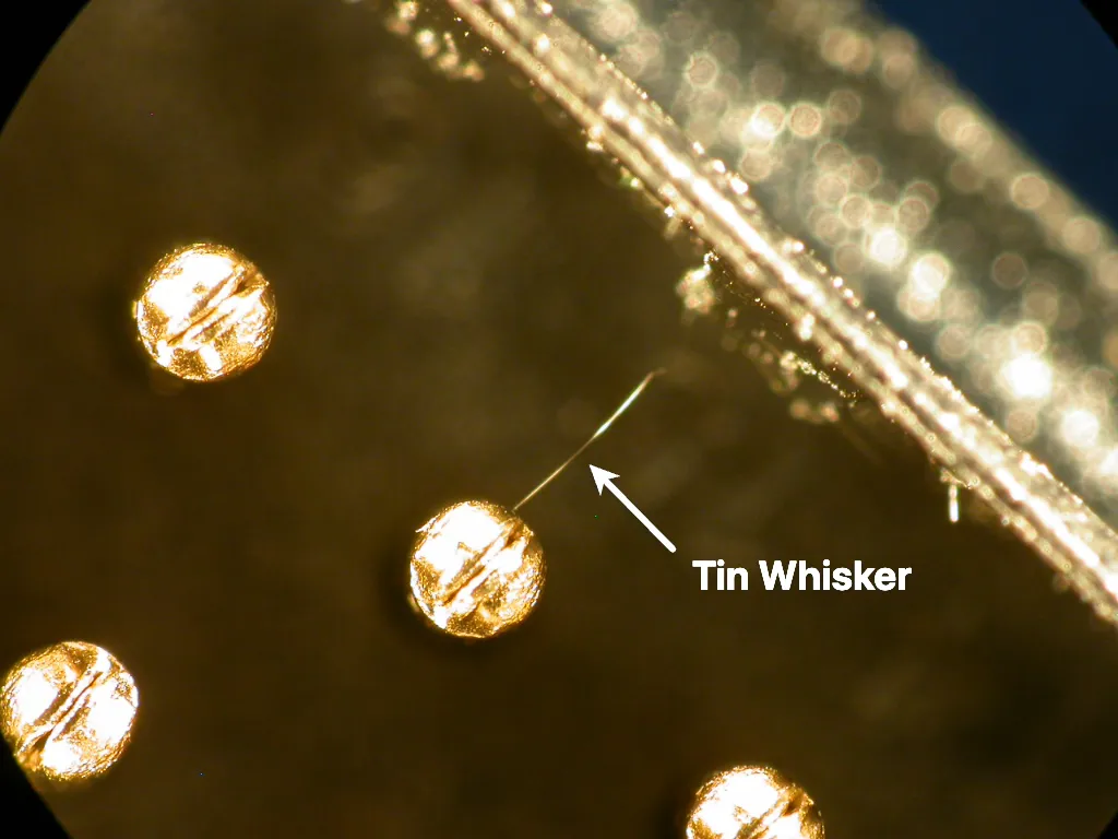
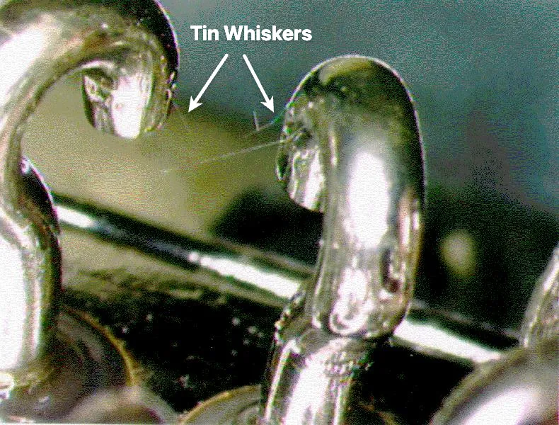
A tin whisker is an electrically conductive, mono-crystalline structure that grows spontaneously from tin-plated surfaces, especially bright electroplated tin. IPC-D-620A documents growth rates of several millimeters per year and lengths exceeding 10 mm in rare cases, and notes that whiskers survive high vibration and shock and can conduct significant power before melting [2]. NASA’s own briefing is refreshingly honest about the physics. The growth mechanism is unknown, and no theory yet predicts whisker density or length versus time [11].
A hair-thin crystal sounds like it should be a minor fault, and sometimes it is, causing nothing more than a parametric deviation before it burns open [2][11]. The catastrophic case is far worse: under certain electrical and atmospheric conditions, a whisker short can vaporize into a conductive plasma of metal ions, forming an arc capable of carrying hundreds of amps [11].
Documented Tin Whisker Failures
This is not a theoretical risk. In mid-1998, Hughes HS601-bus satellites began losing satellite control processors (SCP) on orbit. Investigators narrowed the most probable cause to a tin-plated latching relay inside the SCP, where a crystal less than the width of a human hair could bridge a relay terminal to its case [11]. Each satellite carried a primary and one redundant SCP, so losing both meant losing the mission. Several commercial satellites suffered exactly that [12]:
| Satellite | First SCP failure | Second SCP failure | Outcome |
| GALAXY VII | 1998 | 2000 | Complete loss [12] |
| SOLIDARIDAD 1 | 1999 | 2000 | Complete loss [12] |
| GALAXY IIIR | 2001 | 2006 | Complete loss [12] |
| OPTUS B1, DBS-1, PAS-4, DirecTV 3 | — | — | Partial losses [12] |
NASA’s failure history extends the list beyond satellites to military radar, missile systems, and a nuclear plant trip [12].
The solution is lead. The IPC-D-620A standard defines tin containing less than 3% lead as “lead-free tin” and considers it a material prone to whisker formation [2]. Industry practice goes even further. Connector manufacturer AMP has stated that, wherever possible, it specifies a tin-lead alloy in a 93/7 ratio to slow whisker growth [11]. The IPC-HDBK-620 standard states this very clearly for cable and harness components: avoid pure tin plating, especially bright tin, to minimize the risk of whisker formation [7]. The addition of lead suppresses whisker growth, which is precisely the property that was lost during the transition to lead-free materials.
Why Isn’t Lead Used in Solder Anymore? RoHS, Bans, and Exemptions
Mainly because its use in most electronics has become illegal, not because a more reliable alternative was found. The EU RoHS directive took effect for electronics placed on the market from July 2006 [25], and the current recast, Directive 2011/65/EU, restricts lead to a maximum concentration of 0.1% by weight in homogeneous materials [8]. Global supply chains followed the EU rule, so lead-free became the default even where no law required it.
When Was Lead Solder Banned?
Here, two different bans are being conflated. In the case of electronics, the EU’s RoHS rules have applied since 1 July 2006, the date set by the original directive, 2002/95/EC [25]. As for plumbing systems in the U.S., the Safe Drinking Water Act banned the use of solder containing more than 0.2% lead in drinking water systems as early as June 1986, twenty years earlier and in connection with an entirely different route of exposure [17]. And in the case of military and space equipment, leaded solder has never been banned.
RoHS Exemption: Who Still Gets to Use Lead and Why
The exemptions are written into the directive itself, and they work in two different ways.
Article 2(4) is the first, and it does not grant permission to anybody. It marks where the directive’s authority stops. Equipment necessary to protect the essential security interests of member states, including arms, munitions and war material intended for specifically military purposes, and equipment designed to be sent into space, sit outside its scope entirely [8]. A missile guidance board is not exempt from RoHS. RoHS has nothing to say about it at all: no 0.1% limit, no compliance file, nothing to renew.
Annex III works the other way round. Here the product genuinely is covered and has to meet the limit like any other, but the directive keeps a list of individual uses of lead that are allowed anyway. Entry 7(a) is one of them: lead in high-melting-temperature solders, meaning lead-based alloys that are 85% lead or more [8]. Those are the alloys IPC-HDBK-620 calls for when a connection has to survive temperatures above the melting point of ordinary Sn63Pb37 [7], so removing them would have removed the capability, not just the material. The difference between the two mechanisms is worth keeping straight: an Article 2(4) exclusion is permanent, while an Annex III entry is a permit with a clock on it, granted for a limited period and kept alive only if someone applies to renew it at least 18 months before it expires [8].
An exemption removes a legal obligation, not an engineering risk. Nobody forces these programs to go lead-free, but nothing forbids it either, and lead-free arrives through the parts bin regardless, because the supply chain moved whether high-reliability users wanted it to or not. So the standards set terms for it. NASA-STD-8739.6B requires PCB assembly suppliers to conform to SAE GEIA-STD-0005-1A and -2A at control level 2C for lead-free materials [5]. IPC-D-620A sets the same kind of condition for Class 3 hardware, the top of the three IPC product classes, covering equipment where performance on demand is critical, downtime cannot be tolerated and the end-use environment may be uncommonly harsh, such as life support systems [1]. For that hardware, whenever lead-free tin is a performance or reliability concern, a Lead-Free Control Plan conforming to SAE GEIA-STD-0005-1 and -2 is required, and the user is responsible for choosing the control level from the standard’s scheme of 1, 2A, 2B, 2C and 3 [2]. In high-reliability work, lead-free is not forbidden. It is treated as the risk the test data says it is.
When Should Lead-Free Solder Be Used?
Use lead-free solder when the product falls under RoHS or a similar regulation, which covers most consumer and commercial electronics sold in regulated markets. Once those rules apply, lead-free isn’t optional, it’s law and supply-chain reality [8]. For hobby work, repair, and prototyping outside RoHS scope, either alloy works, and leaded is easier to use and inspect thanks to its lower melting point and shiny, familiar fillets [1][13]. For exempt high-reliability work, follow the program, usually tin-lead per the contract’s workmanship standards, or lead-free only under a formal control plan (for example, NASA’s control level 2C or an IPC-D-620A Lead-Free Control Plan) [2][5].
One rule holds everywhere: do not mix different solders in the same joint. The NASA-DoD data shows SnPb/SnPb and Pb-free/Pb-free systems are both more reliable than mixed joints, and joints dominated by lead-free content in a mix perform worst of all. Reworking a lead-free joint with SnPb restored it to the reliability of a joint built that way from the start, because rework replaces the old solder rather than blending the two. Where both alloys end up in the same joint by accident, the result was the least reliable configuration measured [10].
Is Lead Solder Dangerous? Solder Fumes and Safety
Less than its reputation, if you control the right pathway. The smoke rising from your soldering iron is flux, not lead, and lead mainly enters a solderer’s body through ingestion when it is transferred from the hands to the mouth, which is a risk hygiene measures manage well [15][19].
The physics does the first half of the work. A soldering iron runs around 315–370 °C, while lead does not boil until 1749 °C [26]. In a controlled chamber study of intensive manual soldering with Sn63Pb37, 1,680 joints over four hours, mean airborne lead measured 0.176 µg/m³ [15], about 170 times below the EU occupational exposure limit of 30 µg/m³ set by Directive (EU) 2024/869 [9][15].
The visible fume is colophony (rosin) from the flux core, and it is the real airborne hazard. It is a respiratory sensitizer causing occupational asthma in electronics workers, documented since the 1970s [16]. This is exactly what fume extraction is for, and NASA-STD-8739.6B points you at the OSHA rules covering exhaust ventilation and fume extractors [5]. Note that lead-free changes nothing here except making it slightly worse, since a hotter tip drives more of the same flux into the air.
If lead gets into you, it mostly gets in through your mouth. Lead particulate settles on hands and bench surfaces and transfers to food and cigarettes. The same chamber study also estimated the effect on blood lead, and the rise came out negligible against background [15]. The standards already cover this as contamination rules: IPC/WHMA-A-620E bans eating, drinking, and smoking in the work area [1], and NASA-STD-8739.6B bans the same wherever workmanship processes are applied [5]. Wash your hands, keep food off the bench, and the main exposure route is closed.
Can solder fumes cause cancer?
Not on current evidence. The documented harm from solder-flux fume is occupational asthma from colophony (rosin) — a respiratory sensitizer and a leading cause of occupational asthma, not a recognized carcinogen [16][20]. Studies specific to soldering are limited and point to airway effects, not cancer [21][22]. Lead in the fume is negligible at soldering-iron temperatures, as the chamber measurements above show [15]. So the fume is worth respecting, just not for the reason most people fear it.
Is it safe to solder indoors?
Yes, with ventilation or fume extraction. The airborne concern is flux fume [16], so the control that matters is capturing the plume at the source, with a fume extractor or local exhaust. This holds for leaded and lead-free alike.
What to do after inhaling solder fumes
If you’ve been breathing solder fume, move to fresh air. If you develop persistent wheeze, chest tightness, or asthma-like symptoms that recur when you solder, see a doctor and mention colophony specifically, since sensitization is the documented risk and it worsens with repeated exposure [16]. Also make sure the extraction is working properly before the next session.
Conclusion
The leaded vs lead-free question has a regulatory answer and an engineering answer. Regulation is the easy half: if RoHS covers your product, it is lead-free, and has been since 2006 [25]. Military and space hardware sits outside that scope entirely [8]. Engineering is where the real choice lives. Tin-lead still wins where thermal cycling, vibration, and tin whiskers threaten hardware that cannot be recalled from orbit, which is why high-reliability programs like NASA still specify tin-lead for their most critical hardware, and hold lead-free to a formal control plan when they do use it. So match the alloy to the mission, then stay with it. Joints that end up with both alloys in them were the least reliable configuration the NASA-DoD program measured [10].
References
[1] IPC/WHMA-A-620E, Requirements and Acceptance for Cable and Wire Harness Assemblies. IPC/WHMA, October 2022.
[2] IPC-D-620A, Design and Critical Process Requirements for Cable and Wiring Harnesses. IPC, December 2021.
[3] IPC-A-610D, Acceptability of Electronic Assemblies. IPC, February 2005. (Superseded revision. The current revision is IPC-A-610J, released April 2024; the visual acceptance criteria cited are stable across revisions.)
[4] IPC/EIA J-STD-001C, Requirements for Soldered Electrical and Electronic Assemblies. IPC/EIA, March 2000. (Superseded revision. The current revision is J-STD-001J, released April 2024; the baseline alloy designations cited are stable across revisions.)
[5] NASA, NASA-STD-8739.6B: Implementation Requirements for NASA Workmanship Standards. February 2021. https://standards.nasa.gov/standard/NASA/NASA-STD-87396
[6] NASA, NASA-STD-8739.3: Soldered Electrical Connections. December 1997. (Cancelled in October 2011; per NASA-STD-8739.6B §9.3.1, mission-hardware soldering is now covered by IPC J-STD-001GS, not by the 8739.6 series itself.)
[7] IPC-HDBK-620, Handbook and Guide to Supplement IPC/WHMA-A-620. IPC, April 2018.
[8] Directive 2011/65/EU of the European Parliament and of the Council of 8 June 2011 on the restriction of the use of certain hazardous substances in electrical and electronic equipment (RoHS recast), OJ L 174, 1.7.2011. https://eur-lex.europa.eu/legal-content/EN/TXT/?uri=CELEX:32011L0065
[9] Directive (EU) 2024/869 of the European Parliament and of the Council of 13 March 2024 amending occupational exposure limit values for lead and its inorganic compounds, OJ L, 2024/869, 19.3.2024. https://eur-lex.europa.eu/legal-content/EN/TXT/?uri=CELEX:32024L0869
[10] NASA-DoD Lead-Free Electronics Project, Joint Test Report, Final, December 2011. https://www.dau.edu/artifact/nasa-dod-lead-free-electronics-project-joint-test-report
[11] H. Leidecker and J. Brusse, “Tin Whiskers: A History of Documented Electrical System Failures,” NASA Goddard Space Flight Center / QSS Group, briefing to the Space Shuttle Program Office, April 2006. https://nepp.nasa.gov/whisker/reference/tech_papers/2006-Leidecker-Tin-Whisker-Failures.pdf
[12] NASA Goddard / NEPP, “Whisker Failures,” updated April 2026. https://nepp.nasa.gov/whisker/failures/
[13] AIM Solder, Sn63/Pb37 Solder Alloy Technical Data Sheet, Rev NF5. https://www.mouser.com/datasheet/2/10/alloy_sn63_pb37_tds-3540023.pdf
[14] AIM Solder, SAC305 Lead-Free Solder Alloy Technical Data Sheet, Rev NF7. https://aimsolder.com/wp-content/uploads/alloy_sac305_tds.pdf
[15] B. Kerger et al., “Small chamber study of lead exposures from manual soldering of microelectronics,” Human and Ecological Risk Assessment: An International Journal, 2020. https://www.tandfonline.com/doi/full/10.1080/10807039.2020.1730690
[16] P. S. Burge, M. G. Harries, I. M. O’Brien, and J. Pepys, “Respiratory disease in workers exposed to solder flux fumes containing colophony (pine resin),” Clinical Allergy, vol. 8, no. 1, pp. 1–14, 1978. https://doi.org/10.1111/j.1365-2222.1978.tb00441.x
[17] US EPA, “Use of Lead Free Pipes, Fittings, Fixtures, Solder, and Flux for Drinking Water” (SDWA §1417). https://www.epa.gov/sdwa/use-lead-free-pipes-fittings-fixtures-solder-and-flux-drinking-water
[18] NASA Kennedy Space Center, KSC-DE-512-SM: Ground Systems Development Standard, Revision M-1 (Rev M, Change 1), 15 January 2025 (active). §9.10(c). https://standards.nasa.gov/standard/ksc/ksc-de-512-sm — PDF: https://standards.nasa.gov/system/files/tmp/KSC-DE-512-SM_RevM-Change1.pdf
[19] A. Julander, K. Midander, S. Garcia-Garcia, P. Vihlborg, and P. Graff, “A Case Study of Brass Foundry Workers’ Estimated Lead (Pb) Body Burden from Different Exposure Routes,” Annals of Work Exposures and Health, vol. 64, no. 9, pp. 970–981, 2020. PMID 32566942. https://doi.org/10.1093/annweh/wxaa061
[20] S. Sadhra, I. S. Foulds, et al., “Colophony—uses, health effects, airborne measurement and analysis,” Annals of Occupational Hygiene, 1994. PMID 7978961. https://pubmed.ncbi.nlm.nih.gov/7978961/
[21] A. Mendy et al., “Work-related respiratory symptoms and lung function among solderers in the electronics industry: a meta-analysis,” Environmental Health and Preventive Medicine, 2012. PMID 21879344. https://doi.org/10.1007/s12199-011-0236-8
[22] Y. Kim et al., “Welding and brazing fumes and lung cancer risk: a systematic review and meta-analysis,” Journal of Occupational Medicine and Toxicology, 2026. https://doi.org/10.1186/s12995-026-00512-w
[23] AIM Solder, Sn60/Pb40 Solder Alloy Technical Data Sheet, Rev NF3. https://www.aimalloys.com/sites/default/files/alloy_sn60-pb40_tds.pdf
[24] Chip Quik, Solder Bar Sn62/Pb36/Ag2 (BARSN62PB36AG2) Technical Data Sheet, Rev 1.0. https://www.chipquik.com/datasheets/BARSN62PB36AG2.pdf
[25] Directive 2002/95/EC of the European Parliament and of the Council of 27 January 2003 on the restriction of the use of certain hazardous substances in electrical and electronic equipment (RoHS 1), OJ L 37, 13.2.2003, p. 19. Art. 4(1) sets the 1 July 2006 application date; repealed and replaced by Directive 2011/65/EU. https://eur-lex.europa.eu/eli/dir/2002/95/oj/eng
[26] Royal Society of Chemistry, Periodic Table: Lead (element 82). Melting point 327.462 °C, boiling point 1749 °C. https://periodic-table.rsc.org/element/82/lead
[27] WETEC GmbH, Lötdrähte bleifrei, Lötdraht bleifrei Silver Ag3.8, catalogue 2007, chapter 5, printed page 254. Alloy L-Sn95.5Ag3.8Cu0.7, melting point 217 °C. Art. no. 554743 (Typ Silver 32, 0.5 mm, 500 g). https://www.wetec.hu/file-upload/cnt_5_Wetec_2007_Kapitel_5.pdf