 Skip to content

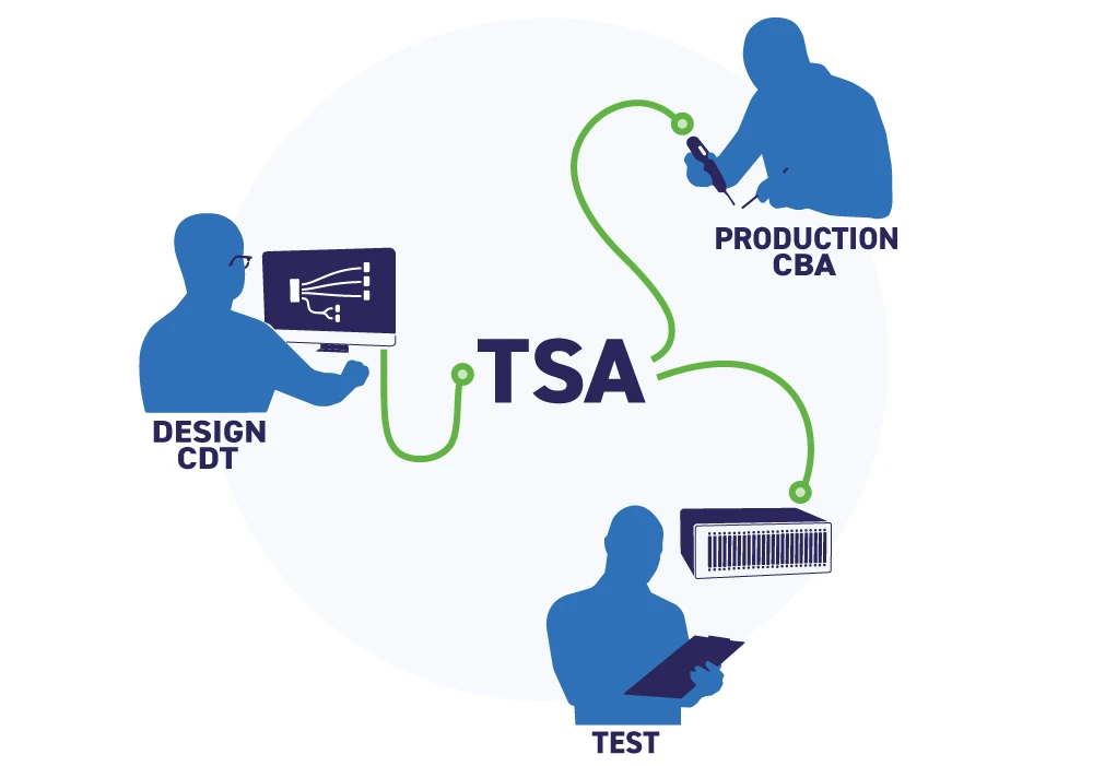
A custom cable assembly passes through three stages: design, manufacture, and test. On most production lines those stages run on three separate sets of data: a schematic, a set of build notes, and a test program, each maintained separately and each able to drift out of agreement with the others. A wire gauge that was correct on the drawing and wrong on the build sheet. A pin reassigned in design but never updated in the test program. These differences rarely surface on the bench, they surface in service.
Our in-house Test System Architect (TSA) removes that separation. TSA is a suite of tools for designing test systems, and the Cable Design Tool (CDT) is the tool within it that makes this possible for cable assemblies. The design a customer creates and signs off in CDT becomes the single source of data for everything that follows: the manufacturing documentation, the build at the bench, and the test procedures. The assembly is built and verified against the design that was approved, not against a second-hand interpretation of it.
The design is the specification
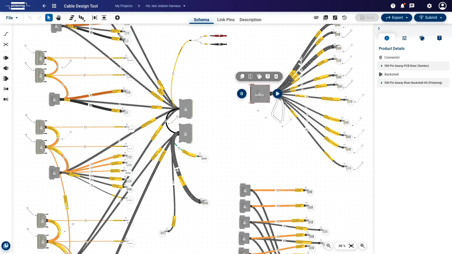
CDT is a browser-based tool for building a cable assembly graphically, either from scratch or from a library of our standard cable sets. The design is not a drawing that later gets translated into manufacturing data, it is the manufacturing data. A completed CDT design holds:
- Full signal routing: which conductor connects to which pin, at both ends
- Wire types and gauges for every path
- Connector and backshell selection
- Path lengths, plus screening and sleeving details
- Labels: signal names that can be printed on wire ends and along paths for traceability
Once the customer signs off, that approved design carries through every stage as a single record. The same data drives the build and the test, with nothing re-entered or re-interpreted between them, so the connectivity the customer approves is the exact connectivity that is built and verified.
A guided, automated build — down to a single piece
The build is run by our in-house Cable Build Assistant, which works directly from the approved design rather than from a printed instruction the assembler has to interpret. It shows exactly which wire connects to which pin, and which wire type and gauge to use, guiding the build step by step.
- It removes the interpretation step between design intent and physical build
- It holds complex, high-pin-count, mixed-connector assemblies to the design without relying on operator memory
- It applies to a one-off the same way it applies to a production run (there is no minimum quantity for the automation to apply)
Driving the build straight from the approved design is what shortens build time and reduces the fail rate. That matters most for low-volume, high-mix work, where most builds are small quantities and the cost of a manual miswire is highest.
“We didn’t have to explain how our schematic should be interpreted. All the details regarding wire types and gauges were within the design tool.”
Test Engineer, major airline
Two-stage verification
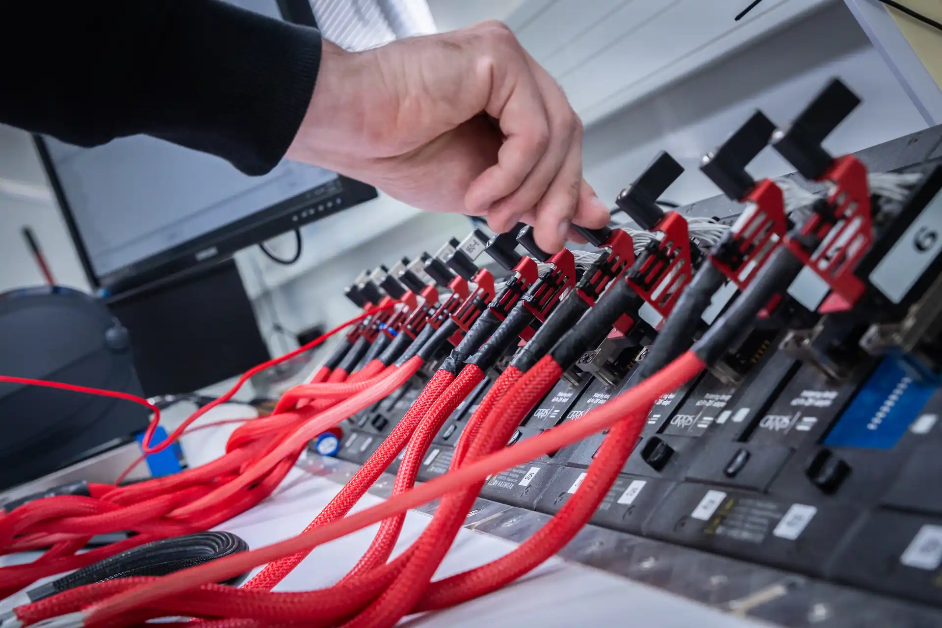
Verification happens in two stages. The first is part of the build and is driven directly by the approved design: as the Cable Build Assistant guides each connection, it checks the pin-out in process, confirming every conductor lands where the CDT design specifies. A misplaced wire is caught while the cable is still on the bench, so it works as a continuous pre-test. The second stage is a separate electrical test on a Cirris tester, where every finished assembly runs a defined sequence:
- Low-voltage tests (4 V, 1 mA to 1 A): continuity checks for shorts, missing contacts and mis-wires; 4-wire path resistance measurement (0.001 to 10 Ω, ±2% ±0.001 Ω)
- High-voltage tests (100 V to 2 kV DC): insulation resistance (5 MΩ to 1 GΩ, ±10%); dielectric withstand
The 4-wire (Kelvin) method removes lead and contact resistance from the measurement, so reported path resistance reflects the cable rather than the test fixture. The pin-out check confirms the assembly matches the approved design, the Cirris test then confirms its electrical integrity, so every cable leaves the facility verified on both counts.
Proof: a 131-signal HIL test station harness
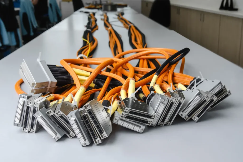
This workflow built and verified a four-part wiring harness for a major airline’s fuel-control-system hardware-in-the-loop (HIL) test station. The harness carried 131 signals across 28 D-type connectors, four 160-pin DIN 41612 connectors, two 500-pin SEARAY connectors and four banana jacks, using more than 2 km of double-screened wire across four gauges.
The airline’s own engineers produced the design in CDT. At sign-off, Cable Build Assistant drove the build directly from that design, and the harness was verified against the test sequence above. As the airline’s Test Engineer put it, the build data did not need to be explained, the wire types and gauges were already in the design tool, and the assemblers worked straight from it. The finished harness worked as soon as it was connected between the fuel control system and the HIL station.

Case study
A Major Airline Selects Pickering for Fuel Control System HIL Test Station Harness
The result
Integrating design, manufacturing, and testing into a single approved design delivers three things you can rely on: a build that matches the approved design without re-interpretation, a test that measures the cable against that same design, and a reorder placed years later that is built and tested against the exact specification on file. The automation that makes this possible is not reserved for volume. It applies from the first piece.
