 Skip to content
How to Import Pinouts Using a CSV File | Cable Design Tool Tutorial
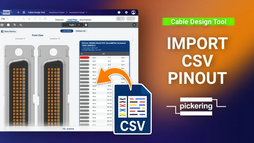
Cable Design Tool Tutorial The Cable Design Tool lets you import a complete pinout from a CSV file instead of linking every pin by hand. For cable assemblies with a large number of conductors, this is the faster and safer route: you build the pinout in a spreadsheet and bring it in all at once. This guide covers the full workflow, from exporting a template CSV to importing pinouts for twisted pair cables. Step 1 Make sure the basics are in place Before using the CSV import, you’ll need the cable assembly foundations in place: selected connectors, the right wires, and a linked path. Then open the pinout view: select the path you want to work on and click the Link Pins icon. Step 2 Link a few pins manually and export a template CSV Once you’re in the pinout view, link one or a few pins manually first. This lets you export a correctly formatted CSV file that you can edit externally and import back in. To export, click the Export CSV button at the top of the pinout table. Step 3 Edit the CSV file Open the exported CSV file. The structure mirrors the pinout view directly: Column A: pin names for the left-side connector Column B: pin numbers for the left-side connector (e.g. starting at 151 for the fourth path of a 200-pin connector) Column C: pin numbers for the right-side connector (for flying leads, always starting from 1 regardless of how many paths the cable has) Column D: names for the flying leads on the right side. Useful if you want them printed on heat shrink at the wire ends during manufacturing (see example). Columns B and C are the critical ones: they define exactly which pins on the left side connect to which flying leads on the right. Step 4 Import the CSV and save Once your CSV is edited and saved, you’re ready to import. Before you do, unlink all wires in the pinout view first. Then click the CSV Import button and select your file. The pinout imports immediately. To save the changes, click Apply Changes in the top right corner. Step 5 CSV variation, pins without names If you don’t need to assign names to the flying leads, you can simplify the CSV: define which pin on the left (Column A) connects to which flying lead on the right (Column B). Without the name columns, the pin numbers shift left into Columns A and B. After the import, the pins are linked without names. If you want to add pin names or make further changes, you can edit the pinout manually at any point. Step 6 CSV variation, twisted pair cables For twisted pair cables, the CSV structure is slightly different. Each twisted pair is split into two sections, Wire A and Wire B, with a blank column between them that must stay empty. For example, when working with a 50-core twisted pair cable from 3M: the first wire (black with red stripes) links pin 1 on the right to pin 1 on the left, and the second wire (red with black stripes) links pin 49 on the right to pin 49 on the left. Export a template CSV after linking the first pair to see this structure in action. As with single wires, you can choose whether or not to include pin names. That covers the complete CSV workflow, from single-core cables to multi-core twisted pair cables, with various naming options.
How to Add a Custom Connector | Cable Design Tool Tutorial
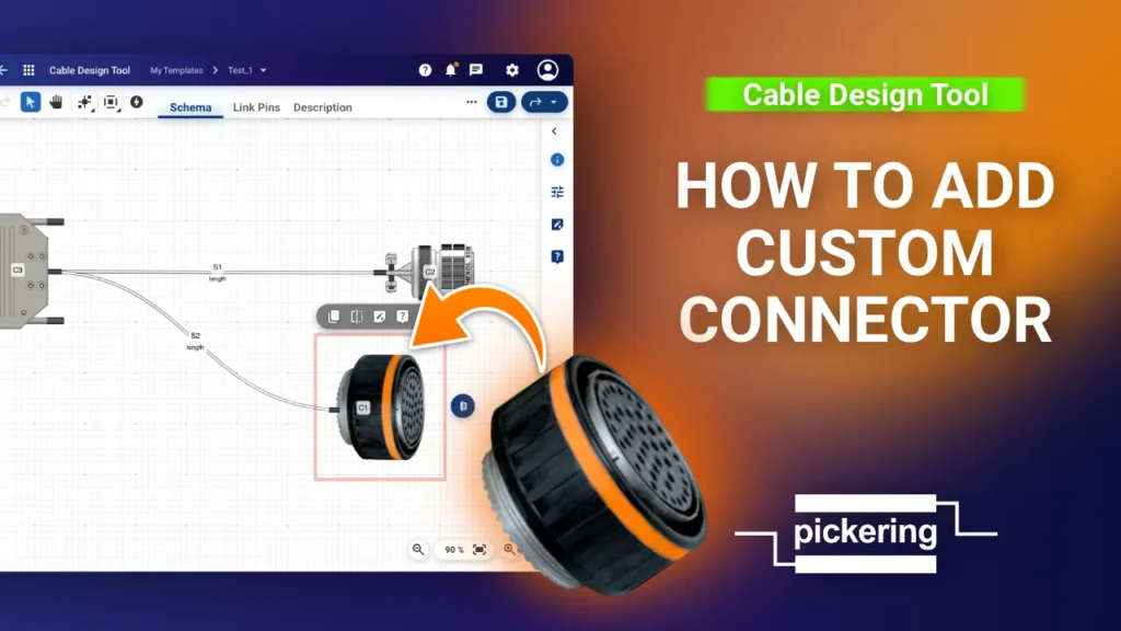
Cable Design Tool Tutorial The Cable Design Tool lets you add custom connectors directly in your design when the part you need isn’t in the library. This guide covers the full process, from creating the connector to linking its pins in the pinout view. Step 1 Open the custom connector editor First, right click an empty space on the canvas to add a connector, then click Select Connector to open the filter view. Search for your connector. If nothing matches, the Create custom connector button appears. You can also start one anytime from the button in the right panel. Both open the connector editor. Step 2 Add a picture of the connector Once the connector editor opens, click the image icon and locate the file. The image serves as a visual reference to help you navigate your project more easily. If you can’t find the exact match, use a similar looking connector, or continue without one. Step 3 Position the image over the outline Rotate and resize the image, placing it over the connector’s outline. Align the backside with the green dots, these are the connection points where you’ll later attach wires. When you’re done editing, click Confirm and leave. Step 4 Fill in the connector details Fill in the connector details, especially the number of pins, gender, and part number. There’s no save button here. The specifications are saved automatically as soon as you click anywhere else. If you have details like the part number for the backshell or pins, add those too. Selecting ground shell enables you to connect shielding to the backshell later, in the pinout view. If you need to add comments, use the description field. Our technicians can help fill in any missing details during the review process. Step 5 Add a wire To complete the connector setup in the pinout view, you’ll need a wire. The quickest way is to duplicate an existing one: click the wire you want to copy, then click the duplicate button that appears. Step 6 Open the pinout view Once the wire connects both connectors, open the pinout view: click the wire to select it, then click Link Pins from the toolbar that appears. Here you can set up the connector’s parameters. For a circular connector, settings like the number of columns or pin arrangement don’t apply. For a MIL-SPEC connector, select pin naming based on that standard. Step 7 Link the pins Link the pins of the existing connector with the newly added one. For simple sequential linking, use Autolink. Step 8 Save your changes The connector is now linked. To save the changes, click Apply changes. The custom connector is now defined, linked, and part of your design. Any missing details get checked by our technicians during the review process.
